In robotic applications, the most common tasks are the transporting tasks. Arch-Gate Trajectory is the core concept behind transporting tasks. All kinds of motion trajectories are based on the Arch-Gate Trajectory. Complex transporting tasks such as Unloading/Loading or Palletizing are based on the integration of these trajectories.
When a robot needs to move an object from Point A to Point B, the robot needs to lift the object straight up for some distance before moving towards B to prevent rubbing or collision with the surface. The point after lifting from A is A'. To minimize the transportation time, the robot should carry the object to a point above B, named B'. The robot will then place the object gently straight down at Point B. The trajectory of A -> A' -> B' -> B is Arch-Gate shaped. For the next pickup and place, the robot will return to Point A in a reversed trajectory, which is B ->B' ->A' ->A. This reversed trajectory can effectively prevent the end effector on the robot from causing displacement to the object already placed at point B and the next object waiting at Point A. According to the actual onsite situation, the robot sometimes can use trajectory of B ->A' -> A, B->B' ->A , or even B->A to return to the original pickup Point.
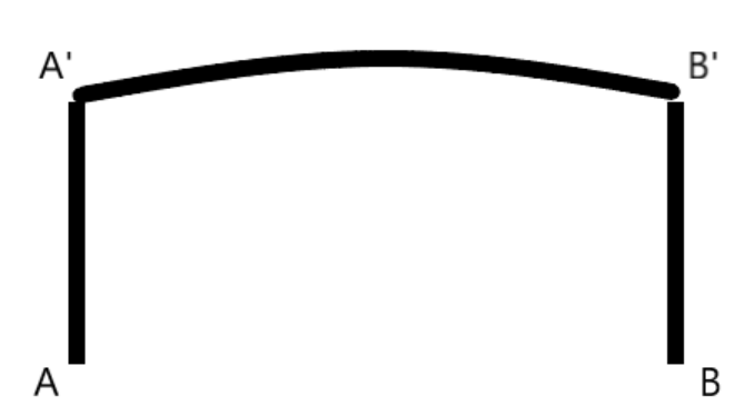
First, we will start with the basic fetching and returning tracks, namely track A -> A' -> B' -> B and track B->B'->A'->A. As shown in the figure above, the four paths A -> A', B' -> B, B->B', and A'->A should all be straight lines, which minimizes the negative effects of displacement, friction, and collision. The two paths A' -> B' and B' -> A' are not necessarily straight lines. For most robots, although a straight line is the shortest route, it is not necessarily the fastest route. Joint interpolation is traditionally used. It ensures that the robot can complete the motion path in the most efficient and comfortable means possible. Joint interpolation can also avoid potential singularities and other problems such as multiple solutions of the target point.
The Elite robot uses P variables and V variables to store coordinate information.
· The P variable adopts the joint coordinate system to record the angles of all six joints. The advantage of P Variables is that the coordinate position has one unique solution, while the disadvantage is that it is difficult to fine-tune the position and posture of the robot by modifying the angles. In handling tasks, P variables are recommended for the coordinate points in long-distance movement.
· The V variable adopts the Cartesian coordinate system, and the coordinates are recorded in the X Y Z axis and the rotation angle around each axis is recorded as Rx Ry Rz. The advantage is that it is much easier to fine-tune the position and posture of the robot, but the disadvantage is that there are multiple solutions for various positions and postures, resulting in the robot sometimes reaching the target point in a posture that the user does not expect. In handling tasks, V variables are recommended to for coordinate points in short-distance movement.
Therefore, it is recommended to use the P variables to record the positions of point A' and point B', and use the V variables to record the positions of point A and point B.

After the trajectories and variables are planned, the prototype of the program can be started. The requirements of the task are: V1 -> P1 -> P2 -> V2-> P2 -> P1 -> V1 and then repeat, after the process details are:
1. Straight line: P1->V1
2. Straight line: V1->P1
3. Joint: P1->P2
4. Straight line: P2->V2
5. Straight line: V2->P2
6. Joint: P2->P1
The process is then looped back to step 1. The JBI procedures required for the Elite EC series are as follows:

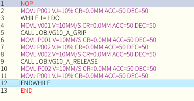
The task handling of objects is inseparable from the picking and placing of objects. Elite robots are suitable for a variety of grippers and air grippers. Elite's engineers have written the required scripts for the ecological cooperation equipment. Users only need to call the JBI subroutine for a specific opening and closing gripper (switch air gripper) or output a specific variable to control the gripper. Assuming that the robot is equipped with OnRobot's VGC10 gripper, after adding the subprogram command to control the gripper at the appropriate position in the program, the program becomes as follows:

At this point, switch the teach pendant to Play mode and change the loop mode to continuous to start repeating the grab and drop jobs. However, after the actual operation, the result is not as smooth as imagined. There are parts of the program that need to be optimized.
The first optimization point: when the program runs for the first time, the robot moves directly from the current position to the point V1, which can easily cause the object to be moved or even collide. Therefore, it is necessary to ensure that the robot starts in standby position P1. The simplest solution is to cut and paste the ninth line of the program in the above figure to the first line (the program is actually the second line, and the original program will be squeezed down from the second line), but for subsequent optimization, here is another solution: append a MOVJ P001 instruction and let other parts of the program loop.
The loop method can use the While command, or you can use the Label command + If command + Jump command to achieve the same effect as the While loop. The example in the figure below will always cycle the pick and place tasks, so there is no need to set a continuous cycle in automatic mode, just use a single cycle.
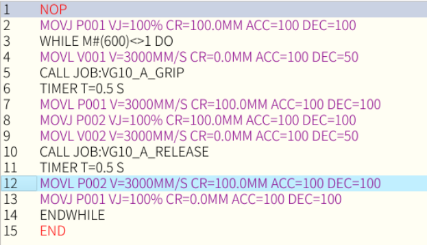
The While 1=1 in the third line can be adjusted according to actual needs, adding another function to stop the task. For example, when the variable M600 is set to 1, the task is stopped. Change the While condition to While M600 <> 1 (or While M600 = 0), and use the button to connect the input port, the stop task can be freely controlled by utilizing the built-in user PLC of the EC to control the M600 or by using the SDK port.

The second optimization point: the robot cycle time is too long, not only is the speed not fast, but the robot stops at every point during the movement. The first problem to solve is the stopping at every point. In the handling task, only the pick-up and placement points need to be stopped, and any other positions need to be smoothly and quickly passed through, which can be achieved by modifying the CR parameters. Simply put, CR is the radius of blending to the next point, and it will not affect the second half of the movement to the next target point. Therefore, the pick-and-place point and the points other than the last point of the program can set the CR as large as possible. (Newer versions prompt the user for the maximum value that can be set)
Next, adjust the program running sped to 100%. In the JBI program, change accelaration for all MOV instruction to maximum. The deccelaration need to be slowed down at picking up position and placing position, but maximum for other position. The MOVL speed need to be adjusted with trail. It's recommended to start from 1000mm/s, then increase 500mm/s for every adjustment if desire faster motion. For MOVJ, it's recommended to start from 30%, then increase 15% for every adjustment after trail. The image below has set both speed to maximum.

The third optimization point: when taking the object, the robot may have moved away before the air gripper has grasped the object. When placing the object, the robot may have moved away before the air gripper has released the object, which may cause the object to fall and be damaged. The robot can be prevented from moving away prematurely by adding a wait instruction. It can either wait for a certain time or wait for the feedback signal of the gripper. There will be built-in waiting commands in the subprograms that control the gripper, and the user can also directly adjust the parameters in the subprograms.
At this point, a handling program based on the Arch-Gate trajectory is completed. Of course, there are still many places that can be adjusted and optimized depending on actual needs.
Example 1. After adding a sensor to confirm that the object has reached the picking position, the robot will perform the picking task; and after confirming that the last carried object has left the placement area through the sensor, the robot will perform the placing task. Suppose two sensors are connected to X004 and X005 respectively. You can add a Wait command to the program to check the status of the pick area and the drop area.

This simple signal waiting function can also be applied in scenarios including, but not limited to, the following:
· Confirming that the lathe processing is completed and open the safety door in the CNC lathe unloading application
· Verify that no other machines or operators are in the pick-and-place area
· Confirm that the relevant lifting columns in the workshop have reached the target height
Example 2. Every time the subroutine to open or close the gripper (start or close the gripper) is called, the subroutine will re-initialize the relevant Lua script, so every time the gripper is opened or closed, it will take a lot of waiting time, so the instruction for the initialization script in the subprogram is extracted separately as an independent subprogram, and it can be run once in the main program, so that the subsequent subprograms that open or close the gripper do not need the initialization script, and the cycle time is improved.

Example 3. The objects to be taken may be randomly placed, so a vision system is required to assist the robot in positioning. The camera completes a data exchange with the robot through scripts. The camera fixed on the robot requires the robot to move to a specific position and send a specific command, and then the robot will receive the calculated feedback signal, target coordinates, and coordinates above the target. In the example in the figure below, the feedback signals are D001 and D010, the target coordinate is P005, and the location just above the target coordinate is P006.
NOP
//Initialize Camera
SET D001 0.0
SET D010 0
STARTLUA INDEX=2
//Wait Camera Ready
WHILE M#(600)<>1 DO
SET D001 0.0
SET D010 0
TIMER T=2.0 S
WAIT D010=1
TIMER T=2.0 S
//Move To photo taking point
MOVJ P011 VJ=100% PL=0
TIMER T=1.0 S
SET D001 5
WAIT D001=0
TIMER T=5.0 S
//Pick Up
MOVJ P006 VJ=100% CR=0.0MM ACC=50 DEC=50
MOVL P005 AV=50.0MM/S PL=0
#CALL JOB:VG10_A_GRIP
TIMER T=0.5 S
MOVL P006 V=3000MM/S CR=100.0MM ACC=100 DEC=100
//Place
MOVJ P002 VJ=100% CR=100.0MM ACC=100 DEC=100
MOVL V002 V=3000MM/S CR=0.0MM ACC=100 DEC=50
#CALL JOB:VG10_A_RELEASE
TIMER T=0.5 S
MOVL P002 V=3000MM/S CR=100.0MM ACC=100 DEC=100
MOVJ P001 VJ=100% CR=0.0MM ACC=100 DEC=100
ENDWHILE
END