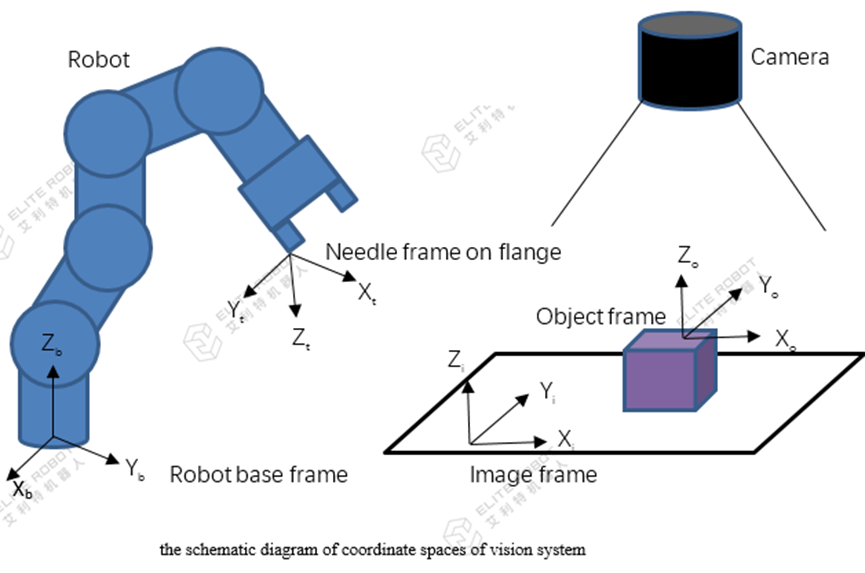
Usually, the camera can be mounted on the robot or other position fixed trestle.
If the camera is mounted on robot, the position of capturing image should be fixed. Otherwise, mouted on the robot, then vision system would be always tracking the robot's pose.
Robot's pose: It is to convert the data under the specified coordinates (such as: user coordinate space or world coordinate space) into the data under the corresponding actual tool coordinates, so its data form is {X, Y, Z, Rx, Ry, Rz}.
Here shows the principal of vision system and how the hand-eye calibration works. (hand means robot, eye stands for camera)

1. Map the image pixel space to physical world space, namely correspond the image pixel value(u,v) to the physical world space (on calibration plane) value(xi,yi)
2. Create a TCP, fix a needle on the flange, calculate the TCP with 4-point method or 7-point method;
3. Create the image frame, use TCP created by step 2 to calibrate image frame against robot base frame, i.e. Ti->b;
4. Put the object on calibration plane within camera FOV, trigger a picture-taking, and get the object frame based on the image frame To->i, then we can get the object frame based on robot base frame To->b by the pose multiplication, i.e. PoseMul(Ti->b,T0->i) in JBI.
5. Keep the object in position, teach the robot to grasp position, and save current TCP pose, i.e. Tt->b, then get the relationship between grasp position and object position Tt->o by the calculation PoseMul(PoseInv(To->b), Tt->b), that’s the final step of calibration and Tt->o is the pose we need to save for future usage.
6. Running, each cycle once the vision gets new object frame, To->i, we can get the object frame based on robot base frame To->b by the calculation PoseMul(Ti->b, To->i). As the relationship between grasp position and object position Tt->o is known. We will get the target grasp pose by the calculation PoseMul(To->b, Tt->o)

