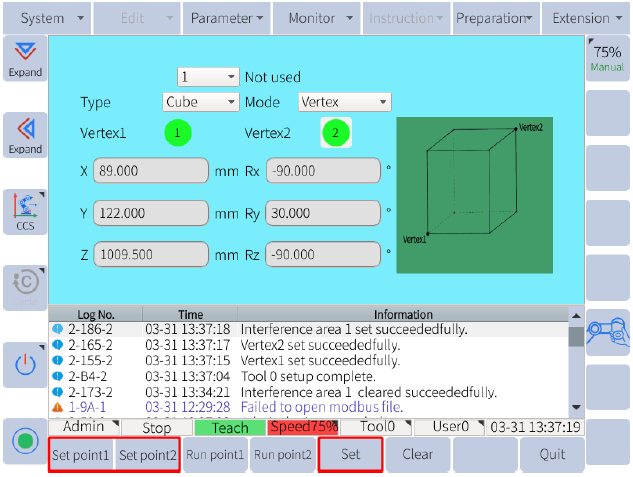
The interference zone is a function that prevents the interference between the robot and other robots or perpheral device. Elite Robots allows the user to configure up to 16 interference zones. The types of interference zone include cubic type and joint type.
The output signals of the interference zone 1 to 16 are using virtual registers from M440 to M455 respectively. If the TCP moves into a designated area configured with cubic interference zone, or a joint enters a certain range configured with joint interference zone, the corresponding M register will go HIGH. If the robot have left the interference zone the signal will return to LOW. If the interference status needs to be shared with an external device, the simplest way is mapping the corresponding M register to a Y register by the PLC program, and wire the corresponding output port on the I/O board to the desired external device. Using Modbus protocol to communicate the robot with the desired device is also an option.
The Cubic Interference Zone is relative to the base coordinate system. (Cartesian coordinate system using the base as origin.) The system determines whether the TCP is inside or outside this area, and output the signal for status. (ON for inside, OFF for outside.)
There are two ways to set cubic interference zone:
 Figure 1. Configuration by Vertex

Figure 2. Configuration by Center Point
The joint interference zone is a function that determines whether the current angle of each joint axis lies in a specified range. If any of the axis angle is less than the configured minimum or bigger than the configured maximum value, the corresponding M register to this interference number will output the status. (ON for inside, OFF for outside.)
P.S. Ignore the XYZ, RxRyRz settings when using Joint Interference Zone.
 图 Figure 3. Joint Interference Zone

