The article "Beginner's Guide for Transporting Tasks with Concept of Arch-Gate Trajectory" introduces the method of making a simple handling program with Arch-Gate trajectories. This article will introduce how to create a simple palletizing program with the concept of Arch-Gate trajectory as the core.
From the trajectory point of view, the palletizing task looks like multiple Arch-Gates are overlapped together, so if many Arch-Gates are made, the frame of the palletizing procedure can be completed. Although this method is feasible, the program will become very tedious, not only will you need to teach a lot of points, but it is also very troublesome to maintain and manage. Rather than overlapping multiple gate frames, make a program that changes the position of one gate post on every run.
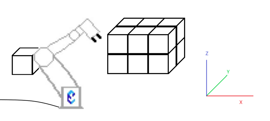
This article will take the following figure as an example to design a palletizing program that places 12 boxes in a 3X2X2 manner. The size of the box is 10cm X 10cm X 10cm. The coordinate system of the robot is parallel to the coordinate system of the palletizing area.
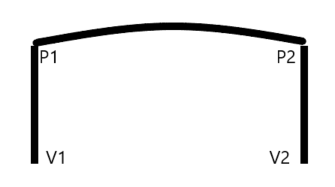
The picture below shows the deformation of a Arch-Gate, which is the core of this palletizing process. The concept of using P variables and V variables has not changed: they are necessary to accurately adjust the position. The V variables are used for points that move a short distance; the P variable is recommended for points that move a long distance. Point V1 is a similar pick-up position. After simply teaching V1, raise the flange vertically and teach a P1 at a suitable height perpendicular to V1. The placement side has multiple points. V2 is the placement point, and the coordinates will be updated according to the current box number that needs to be placed. V3 is perpendicular to the top of V2, which is the position before placement. The height needs to ensure that it will not hit an already placed box, and it will be updated along with the coordinate update of V2. P2 is the general point above the palletizing area. The P3 between P2 and V3 is a very important transition point in the palletizing task, and the coordinates will also be updated according to the coordinate changes of V2.

Without an adaptable P3 point in the palletizing application, two problems might be encountered:
1. When the robot places a box at a point far away, it cannot reach the target point because the joint rotation angle has reached the upper limit during the movement from V3 to V2.
2. When the robot moves from P2 to V3, it enters V3 in a strange posture, causing the box it is holding to hit the robot itself.
Having a P3 point to adjust the joint orientation before moving to V3 can effectively solve both problems.
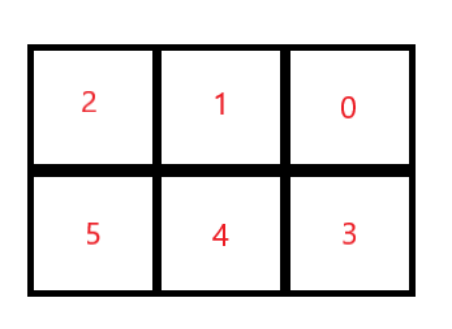
To make it easier to understand the next few steps, the boxes are numbered. Numbering follows a 0-based rule. Layer 0 is numbered 0-5 from right to left, and layer 1 is 6-11. This number also determines the order in which the boxes are transported. The key to this order is to place the farthest box first. Otherwise, during the movement from V3 to V2, the posture of the robot may touch the already placed box.

Open up the basic Arch-Gate handling program of the previous article and start the palletizing program transformation based on this. Note: In practical applications, the place marked with "//(Insert Pick Up Start Signal Here)" needs to insert the command signal of "Pick Up Object", which can be the judgment signal that the box has reached the pickup location.
NOP
MOVJ P001 VJ=100% CR=0.0MM ACC=50 DEC=50
WHILE 1=1 DO
//Pick Up
//(Insert Pick Up Start Signal Here)
MOVL V001 AV=50.0MM/S PL=0
#CALL JOB:VG10_A_GRIP
TIMER T=0.5 S
MOVL P001 V=3000MM/S CR=100.0MM ACC=100 DEC=100
//Place
MOVJ P002 VJ=100% CR=100.0MM ACC=100 DEC=100
MOVL V002 V=3000MM/S CR=0.0MM ACC=100 DEC=50
#CALL JOB:VG10_A_RELEASE
TIMER T=0.5 S
MOVL P002 V=3000MM/S CR=100.0MM ACC=100 DEC=100
MOVJ P001 VJ=100% CR=0.0MM ACC=100 DEC=100
ENDWHILE
END
1. First, correct the cycle conditions. Since there are only 12 boxes to be transported, only 12 cycles are required. A single B variable can be used as a counter for the number of boxes that have been moved. Initialize B000 = 0, change the While condition to WHILE B000< 12 DO, and increase the value of B000 before ENDWHILE.
NOP
SET B000 0
MOVJ P001 VJ=100% CR=0.0MM ACC=50 DEC=50
WHILE B000<12 DO
//Pick Up
//(Insert Pick Up Start Signal Here)
MOVL V001 AV=50.0MM/S PL=0
#CALL JOB:VG10_A_GRIP
TIMER T=0.5 S
MOVL P001 V=3000MM/S CR=100.0MM ACC=100 DEC=100
//Place
MOVJ P002 VJ=100% CR=100.0MM ACC=100 DEC=100
MOVL V002 V=3000MM/S CR=0.0MM ACC=100 DEC=50
#CALL JOB:VG10_A_RELEASE
TIMER T=0.5 S
MOVL P002 V=3000MM/S CR=100.0MM ACC=100 DEC=100
MOVJ P001 VJ=100% CR=0.0MM ACC=100 DEC=100
INC B000
ENDWHILE
END
2. Use comments to divide the program into three parts: the initialization, the calculation, and the movement. The calculation and movement parts need to be updated every cycle.。
NOP
//*********** Initialization ************
SET B000 0
MOVJ P001 VJ=100% CR=0.0MM ACC=50 DEC=50
//---------------------------------------
//
//************ Calculation **************
//---------------------------------------
//
//************** Movement ***************
WHILE B000<12 DO
//Pick Up
//(Insert Pick Up Start Signal Here)
MOVL V001 AV=50.0MM/S PL=0
#CALL JOB:VG10_A_GRIP
TIMER T=0.5 S
MOVL P001 V=3000MM/S CR=100.0MM ACC=100 DEC=100
//Place
MOVJ P002 VJ=100% CR=100.0MM ACC=100 DEC=100
MOVL V002 V=3000MM/S CR=0.0MM ACC=100 DEC=50
#CALL JOB:VG10_A_RELEASE
TIMER T=0.5 S
MOVL P002 V=3000MM/S CR=100.0MM ACC=100 DEC=100
MOVJ P001 VJ=100% CR=0.0MM ACC=100 DEC=100
INC B000
//---------------------------------------
ENDWHILE
END
3. In the movement section, insert the command to move to V003 and P003. Pay attention to the types of MOV instructions and adjustment parameters.。
//************** Movement ***************
//Pick Up
//(Insert Pick Up Start Signal Here
MOVL V001 AV=50.0MM/S PL=0
#CALL JOB:VG10_A_GRIP
TIMER T=0.5 S
MOVL P001 V=3000MM/S CR=100.0MM ACC=100 DEC=100
//Place
MOVJ P002 VJ=100% CR=100.0MM ACC=100 DEC=100
MOVJ P003 VJ=100% CR=100.0MM ACC=100 DEC=100
MOVJ V003 V=3000MM/S CR=1.0MM ACC=100 DEC=50
MOVL V002 V=3000MM/S CR=0.0MM ACC=100 DEC=50
#CALL JOB:VG10_A_RELEASE
TIMER T=0.5 S
MOVL V003 V=3000MM/S CR=10.0MM ACC=100 DEC=100
MOVJ P003 V=3000MM/S CR=100.0MM ACC=100 DEC=100
MOVJ P002 V=3000MM/S CR=100.0MM ACC=100 DEC=100
MOVJ P001 VJ=100% CR=0.0MM ACC=100 DEC=100
INC B000
//---------------------------------------
4. Next comes the calculation part. First, it is necessary to find out which layer, row, and position the current box needs to be placed on. Use a few divisions to get the desired value. The quotient obtained by dividing the value of B000 by the number of boxes in each layer 6 is the layer number information. For example, when moving the sixth box, the value of B000 is 5. 5 is divided by 6 to get 0, and the remainder is 5, meaning the current box is on the 0th floor. Make the remainder 5 be divided by 3, the number of boxes per row, and get the result as 1 with the remainder as 2. This means that the position is at row 0 position 2.

5. Then, in the program's calculation part, the remainder instruction and the division operation instruction can be used to save the number of layers, the number of rows, and the number of digits to the variables B001, B002, and B003 respectively.
//************ Calculation **************
//Layer#
SET B001 B000
DIV B001 6
//Row#
SET B002 B000
MOD B002 6
SET B003 B002
DIV B002 3
//Column#
MOD B003 3
//---------------------------------------
6. Teach the coordinates of the 0th layer, the 0th row, and the 0th position to another V variable, such as V010, so that V002 can be reset easily. The size of the known box is 10cm X 10cm X10 cm, so the spacing of about 105mm is quite suitable. According to the current number of layers, rows, and digits, use the multiplication command to update the coordinates of V002. Note that in this example, V002(0) is the x-direction, which is adjusted according to the number of boxes in the box, V002(1) is the y-direction, which is adjusted according to the number of rows in the box, and V002(2) is the Z-axis direction, which is adjusted according to the number of layers in the box. Adjustment. The addition or subtraction instruction is selected according to the change direction of XY. In this example, the X-direction position decreases according to the increase of the number of boxes; and the Y-direction position decreases according to the increase of the number of boxes. Then use the addition command to update the coordinates of V003 with the updated coordinates of V002.
//Column#
MOD B003 3
//
//Reset V002
SET V002 V010
//Z-axis
SET D000 105.000
MUL D000 B001
ADD V002(2) D000
//Y-axis
SET D000 105.000
MUL D000 B002
SUB V002(1) D000
//X-axis
SET D000 105.000
MUL D000 B003
SUB V002(0) D000
//
//Update V003
SET V003 V002
ADD V003(2) 105
7. Finally, the only points left for the Arch-Gate are P2 and P3. P2 is set to be just above the center of the stacking area, and it is enough to not touch the position of any layer-height box. Then, start the test program. If all V3 and V2 points can be reached without any problem, then directly set the coordinates of P3 to the same as P2. If there are positions that can only be reached by adding intermediate points, then these intermediate points need to be saved to other P variables individually and have them assigned to P3 when needed. During testing, this sample program found that to place boxes 0 and 3 smoothly, a common intermediate point is required. Another common intermediate point is needed for boxes 6 and 9, and another for boxes 8 and 11. This example also reflects that the locations where intermediate points are needed are generally concentrated near the areas farthest and closest to the robot.

8. Teach the three P3 candidates to P010, P011, and P012 respectively. They can also be set with the SETJOINT instruction in the initialization area of the program, which can prevent the variables from being modified by others. (In fact, all reference points including P1, V1, initial V2, and P2 are recommended to be set in the initialization area through SETJOINT or SETPOSE, otherwise if the variables are modified by other users in other programs, the robot will move to the wrong position.)
NOP
//*********** Initialization ************
SET B000 0
MOVJ P001 VJ=100% CR=0.0MM ACC=50 DEC=50
SETJOINT P010 19.354,-54.491,72.265,-109.329,90.500,8.810,0.0000,0.0000
SETJOINT P011 19.904,-73.585,72.264,-93.012,90.538,8.805,0.0000,0.0000
SETJOINT P012 19.878,-109.548,122.590,-107.113,90.541,8.805,0.0000,0.0000
//---------------------------------------
//
9. Then, in the calculation part, let the robot know which P3 it needs to use when moving each numbered box. This can be done with a simple IF instruction.
Box Number | P3 Transfer | Box Number | P3 Transfer |
0 | P10 | 6 | P11 |
1 | P2 | 7 | P2 |
2 | P2 | 8 | P12 |
3 | P10 | 9 | P11 |
4 | P2 | 10 | P2 |
5 | P2 | 11 | P12 |
//
//Update P003
IF B000 = 0 OR B000 = 3 THEN
SET P003 P010
ELSEIF B000 = 6 OR B000 = 9 THEN
SET P003 P011
ELSEIF B000 = 8 OR B000 = 11 THEN
SET P003 P012
ELSE
SET P003 P002
ENDIF
At this point, the palletizing procedure is completed. Below is the full version.
NOP
//*********** Initialization ************
SET B000 0
MOVJ P001 VJ=100% CR=0.0MM ACC=50 DEC=50
SETJOINT P010 19.354,-54.491,72.265,-109.329,90.500,8.810,0.0000,0.0000
SETJOINT P011 19.904,-73.585,72.264,-93.012,90.538,8.805,0.0000,0.0000
SETJOINT P012 19.878,-109.548,122.590,-107.113,90.541,8.805,0.0000,0.0000
//---------------------------------------
//
//************ Calculation **************
WHILE B000<12 DO
//Layer#
SET B001 B000
DIV B001 6
//Row#
SET B002 B000
MOD B002 6
SET B003 B002
DIV B002 3
//Column#
MOD B003 3
//
//Reset V002
SET V002 V010
//Z-axis
SET D000 105.000
MUL D000 B001
ADD V002(2) D000
//Y-axis
SET D000 105.000
MUL D000 B002
SUB V002(1) D000
//X-axis
SET D000 105.000
MUL D000 B003
SUB V002(0) D000
//
//Update V003
SET V003 V002
ADD V003(2) 105
//
//Update P003
IF B000 = 0 OR B000 = 3 THEN
SET P003 P010
ELSEIF B000 = 6 OR B000 = 9 THEN
SET P003 P011
ELSEIF B000 = 8 OR B000 = 11 THEN
SET P003 P012
ELSE
SET P003 P002
ENDIF

//---------------------------------------
//
//************** Movement ***************
//Pick Up
//(Insert Pick Up Start Signal Here)
MOVL V001 AV=50.0MM/S PL=0
#CALL JOB:VG10_A_GRIP
TIMER T=0.5 S
MOVL P001 V=3000MM/S CR=100.0MM ACC=100 DEC=100
//Place
MOVJ P002 VJ=100% CR=100.0MM ACC=100 DEC=100
MOVJ P003 VJ=100% CR=100.0MM ACC=100 DEC=100
MOVJ V003 V=3000MM/S CR=1.0MM ACC=100 DEC=50
MOVL V002 V=3000MM/S CR=0.0MM ACC=100 DEC=50
#CALL JOB:VG10_A_RELEASE
TIMER T=0.5 S
MOVL V003 V=3000MM/S CR=10.0MM ACC=100 DEC=100
MOVJ P003 V=3000MM/S CR=100.0MM ACC=100 DEC=100
MOVJ P002 V=3000MM/S CR=100.0MM ACC=100 DEC=100
MOVJ P001 VJ=100% CR=0.0MM ACC=100 DEC=100
INC B000
//---------------------------------------
ENDWHILE
END
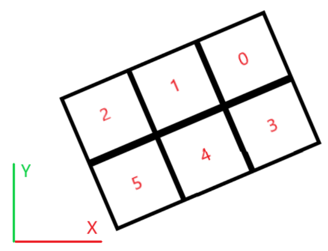
In this example, the coordinate system of the robot and the coordinate system of the palletizing area are parallel, so the position calculation is relatively easy. If the coordinate systems are not parallel, a change in that number of digits or rows will change the coordinates in both the x and y axes. The following code is a demonstration that the coordinate system of the palletizing area has a deviation of about 30 degrees from the coordinate system of the robot. According to the measurement, the change in the number of digits will reduce the x-axis coordinate by 90.932 mm and the y-axis coordinate by 52.500 mm; the change in the number of lines will reduce the x-axis coordinate by 52.500 mm and the y-axis coordinate by 90.932 mm
//Reset V002
SET V002 V010
//Z-axis
SET D000 105.000
MUL D000 B001
ADD V002(2) D000
//Row Offset
SET D000 90.932
SET D001 52.500
MUL D000 B002
MUL D001 B002
SUB V002(0) D000
SUB V002(1) D001
//Column Offset
SET D002 52.500
SET D003 90.932
MUL D002 B003
MUL D003 B002
SUB V002(0) D002
SUB V002(0) D003
If you don't know how to measure the change needed to calculate the X- and Y-axis coordinates, you can use a robot to measure it.
As shown in the figure below, you can use the state of the robot to hold the box to record the position 0, position 1 and position 3 in the three positions V100, V101, and V103 respectively. During the teaching process, the influence of the height deviation can be ignored, but it must be ensured that there is no rotation in the three directions of Rx, Ry, and Rz.
X-axis coordinate change caused by the change of digits = X-axis coordinate of V101 - X-axis coordinate of V100
Y-axis coordinate change caused by the change of digits = Y-axis coordinate of V101 - Y-axis coordinate of V100
X-axis coordinate change caused by the changes in the number of rows = X-axis coordinates of V103 - X-axis coordinates of V100
Y-axis coordinate change caused by the changes in the number of rows = Y-axis coordinate of V103 - the Y-axis coordinate of V100
Then replace the results with the parameters of D000~D003 in the example above.